
Schema-based Ontological Representations of a Domain-Specific Scenario Modeling Language
ACM Subject Categories
Computing methodologies~Modeling methodologiesComputing methodologies~Simulation languagesInformation systems~Ontologies
Keywords
- Model-Based Development
- Simulation Scenario
- SES
Abstract
The first step in designing a domain-specific simulation scenario definition language is constructing its ontology. The recently published Aviation Scenario Definition Language (ASDL) aims at providing a common platform to specify scenarios in the aviation domain. To capture an ASDL ontology, the Web Ontology Language and the Protégé tool was utilized, which was then converted into an XML schema by means of tool automation in the Eclipse Modeling Framework. On the other hand, the System Entity Structure (SES) provides a formal basis to represent the ontological foundations of a domain language. Following the XML Schema representation of SES, a scenario modeling ontology that has been recently published, we illustrate how an equivalent schema for a scenario definition language can be constructed using a domain-specific language ontology-driven approach and SES. We take both approaches to represent the ASDL ontology and prove that the resulting schema produced from these two approaches converge to the same result.
Introduction
The term scenario
has a variety of published definitions from a
vast array of domains. While the term itself has varying meanings, two
definitions represent a scenario in the context of simulation development
and usage. First, a scenario can be defined as a description of the
hypothetical or real area, environment, means, objectives, and events
during a specified time frame related to events of interest (GSD Product Development Group,
2014). Second, a scenario can be defined as a specification of
conditions and situations to be represented by a simulation environment
for its purpose (Durak, Topcu,
Siegfried, & Oguztuzun, 2014). Both definitions agree that a
scenario is a description of important events and conditions needed to
represent a specific order of events which, in this application, occurs
within a simulation environment. Therefore, when developing a simulation
environment which utilizes these events and conditions, it is often a
prerequisite to define the scenarios that will be executed in the target
simulation environment. This concept is known as scenario-based
development.
The Simulation Interoperability Standards Organization (SISO) released guidelines for the creation of simulation scenarios, detailed in (NATO Modelling and Simulation Group MSG-086, 2015). The guideline provides detailed information regarding the development of simulation scenarios, including an overview of available tools and processes. According to (GSD Product Development Group, 2014), a scenario must be well-defined and must be complete, consistent, and comprehensible. Failing to achieve these aspects can lead to incomplete scenario definition and misunderstanding regarding the scope and applications of the simulation environment. As a result, the subsequently designed simulation environment is prone to error and may not reflect what the user originally intended. For a simulation environment that is designed to execute a specific set of scenarios, this misunderstanding can be disastrous.
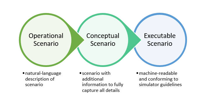
Scenario development is an important part of all phases of the simulation environment development process. It not only defines a specification of a simulation run, but also provides an input for the design and evaluation of the simulation environment itself (Durak, Topcu, Siegfried, & Oguztuzun, 2014). Scenario development can be broken down into the creation of three scenario groups: (1) operational scenarios, (2) conceptual scenarios, and (3) executable scenarios. First, operational scenarios are provided by subject-matter experts (SMEs) in the early stages of development. These scenarios often provide a broad description of the desired events in textual form using natural language. For example, an operational scenario may describe what events occur during the simulation and in which order they should occur. Operational scenarios use domain-specific terminology to describe the events, which can then be identified by the Modeling and Simulation (M&S) expert and incorporated into the simulation ontology. Operational scenarios must be identified before development of the simulation environment, as virtually all simulation requirements are derived from these scenarios. Second, although operational scenarios provide the simulation requirements, they are too broad to provide the details necessary to derive a conceptual model and create a simulation environment. A conceptual scenario adds this detail and additional information to the operational scenarios. These scenarios are often created by an M&S expert in collaboration with an SME. Although similar to an operational scenario, conceptual scenarios should contain all information needed for the simulation environment. In addition, instead of a purely natural language approach, a conceptual scenario is used to create a conceptual model, which elaborates concepts into entities similar to UML classes. These entities contain properties and attributes which describe their roles and associations in the simulation environment. Finally, once the conceptual model is complete and the simulation environment is defined, executable scenarios can be made. An executable scenario is the specification of a specific situation providing all information necessary for preparation, initialization, and execution of a simulation environment (GSD Product Development Group, 2014). These scenarios are ideally specified in a way that allows them to be machine-readable and reusable. These types of scenarios can be seen in Figure 1.
Durak et al. (Durak, Topcu, Siegfried, & Oguztuzun, 2014) propose a model-driven engineering (MDE) approach to the scenario development process using the Eclipse Modeling Framework (EMF). Following MDE principles, scenario development is viewed as the transformation of operational scenarios (defined using natural language) to conceptual scenarios (conforming to a metamodel) to executable scenarios (specified using a scenario specification language) and simulation environment design (following a specific formalism). As the development process occurs, the scenario models are refined and transformed. As a result, the proposed method requires conceptual scenarios to be based on a metamodel which is then transformed into executable scenarios for target simulation environments using a set of rules specific to the target simulation environment. Following this method of model-to-model or model-to-text transformations, a conceptual scenario can be transformed into multiple executable scenarios for multiple target simulation environments. This greatly promotes reuse and simplicity among the M&S community.
During the scenario development process, each scenario should at least specify three main components: (1) the initial state, (2) the course of events, and (3) the termination conditions. As the scenario development process progresses, these three components should be further refined and expanded. The initial state describes the situation at the beginning of the scenario timeline and generally contains information such as date and time, surrounding conditions, and objects. The course of events describes any pre-planned events that occur at a specified time or in a specified order. These events can elicit a response, such as from a trainee using the system, or describe a change in entity association or state, such as an aircraft beginning a turn while en route. Events are often prompted by a trigger condition and each event injects changes to the simulation scenario state to achieve a desired effect or action. Any number of events can occur throughout the scenario timeline. The termination conditions describe the state of the simulation environment where the scenario can be defined as completed or terminated. This can occur via a specific event (such as a successful landing) or other means of measurement (such as achieving a predefined elapsed time) (GSD Product Development Group, 2014).
Scenario-based development and the scenario development process are complex and time-consuming. However, a variety of tools and standards exist to help alleviate these challenges. For operational scenarios, the Distributed Simulation Engineering and Execution Process (DSEEP) describes a generic 7-step process for developing and executing a simulation environment. DSEEP was used by Durak et al. (Durak, Topcu, Siegfried, & Oguztuzun, 2014) when implementing the MDE approach to scenario development. The Coalition-Battle Management Language (C-BML) strives to provide a standard for specifying the course of events within a scenario. For conceptual scenarios, the Base Object Model (BOM) defines a standard for defining and reusing components of models, simulations, and federations. BOM can be used as a base for a simulation conceptual model and in the design of scenarios for interoperable simulations. For executable scenarios, the Military Scenario Definition Language (MSDL) is the most well-known standard for specifying executable scenarios in the military domain (GSD Product Development Group, 2014).
The American Institute of Aeronautics and Astronautics (AIAA) Modeling and Simulation Technical Committee (MSTC) recently launched a working group towards the development of a standard simulation scenario definition language for the aviation domain. However, there are multitudes of challenges which are well introduced in (Jafer & Durak, 2017). First to mention is the complexity of the aviation systems which comes from the large number of systems/subsystems involved, their deep hierarchical system structures, and complicated interrelations and inter-dependencies. Simulation scenario definition conclusively inherits this complexity. Additionally, variability of intended use adds another flavor to complexity. It corresponds to variability in systems modeling both in scope and resolution. As the structure and elements of the modeled air and ground systems vary, the simulation scenario definition also varies. For example, the elements of scenarios may largely differ between the simulations for air crew training and research into pilot vehicle interfaces. Therefore, we are conducting two parallel efforts for developing the simulation scenario definition language of aviation. First to mention, the Aviation Scenario Definition Language (ASDL), proposed by Jafer, Chhaya, Durak, and Gerlach (2016) utilizes the Web Ontology Language (OWL) and Eclipse Modeling Framework. The second one proposed by Durak et al. (2017) utilizes System Entity Structure ontology. Durak et al. (2018) claims that utilizing XML based approaches are key to achieve wide industry acceptance of the standard simulation scenario definition language. Here in this paper we illustrate how equivalent schema for a scenario definition language can be constructed using both OWL ontology and SES based approaches.
Background
Domain-Specific Languages
Domain-specific languages (DSLs) are computer languages tailored to a specific application domain. As a result, DSLs are often more expressive for that particular domain, offering ease of use. This allows domain experts, who may not be familiar with programming and general-purpose programming languages, to use a DSL to express ideas and concepts in their domain, which is commonly not possible otherwise.
DSL development is incredibly difficult as it requires knowledge of the domain and language development expertise, of which few people have both. As a result, the creation of a DSL is often not considered and if so, a DSL rarely evolves into a full-fledged language which can be used within the domain it is intended for (Mernik, Heering, & Sloane, 2005).
Ontology
An ontology describes the concepts and relationships that are important in a particular domain and provides a vocabulary for that domain via a computerized specification of the meaning of terms used in the vocabulary (Yao & Zhang, 2009). Ontologies bridge the gap between people and systems, as ontologies describe domain relationships and objects in an easily understood manner while maintaining the ability to be machine interpretable. As a result, ontologies allow both people and computers to understand and derive new knowledge about the domain in question (Putten, Wolfe, & Dignum, 2008). Therefore, ontologies can be used as a starting point for further development as a domain expands or the ontology embraces new or additional concepts.
The Web Ontology Language (OWL) is a popular format for creating and sharing an ontology. OWL is a semantic markup language for publishing and sharing ontologies on the web. It extends the Resource Description Framework (RDF) vocabulary and enables describing a domain in terms of classes, properties, and individuals (Bechhofer, 2009).
Aviation Scenario Definition Language
First proposed by Jafer, Chhaya, Durak, and Gerlach (2016), the Aviation Scenario Definition Language (ASDL) provides a simple, standardized method for aviation scenario generation from a model-driven perspective. ASDL aims to provide a common mechanism for verifying and executing aviation scenarios, allow for effective sharing of scenarios among various simulation environments, improve the consistency of different simulators and simulations, and enable the reuse of scenario specifications. By creating a common, standardized language for defining aviation scenarios, the duplicate effort often seen in the aviation simulation scenario generation process can be avoided. Developed in the Eclipse Modeling Framework (EMF), ASDL is a DSL currently supports four major categories of flight operation scenarios: departure, en route, reroute, and landing, as well as air traffic management concepts such as controller-pilot communication (Chhaya, Jafer, Coyne, Thigpen, & Durak, 2018).
The creation of ASDL and ASDL scenarios follows three major steps: (1) ASDL-specific ontology creation, (2) EMF definition and metamodel creation, and (3) design and implementation of a scenario in the instantiated model. The ASDL ontology is comprised primarily of key terminology defined by the Federal Aviation Administration (FAA), as well as procedures and operations that are communicated between the pilot and air traffic control (ATC). All ontology terms currently included in ASDL were obtained from (Federal Aviation Administration, 1995), (SESAR, 2018), and (Federal Aviation Administration, 2012). In the interest of reusability, the ASDL ontology focuses on all aspects of a flight, including the physical aircraft, ATC communications and procedures, and pilot communications and procedures. By including such aspects, the ontology can be used in all forms of aviation simulators, including ATC simulators and pilot training simulators.
SES
A fundamental representation of Discrete Event System Specification (DEVS) (Zeigler, 2000) hierarchical modular model structures is the System Entity Structure (SES) (Zeigler, 1984) which represents a design space via the elements of a system and their relationships in a hierarchical and axiomatic manner. SES is a declarative knowledge representation scheme that characterizes the structure of a family of models in terms of decompositions, component taxonomies, and coupling specifications and constraints. The SES is a formal ontology framework, axiomatically defined, to represent the elements of a system (or world) and their relationships in hierarchical manner making a family of hierarchical DEVS models (Pawletta, Schmidt, Zeigler, & Durak, 2016). Figure 2 provides a quick overview of the elements and relationship involved in a SES.
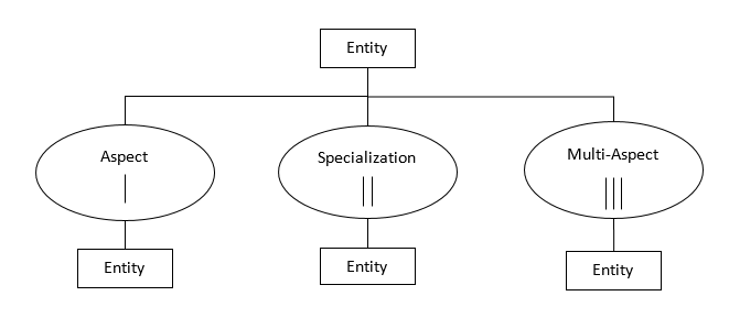
Entities represent things that have existence in a certain domain. They can have variables which are assigned a value within a given range and type. An Aspect expresses a way of decomposing an object into more detailed parts and is a labeled decomposition relation between the parent and the children. MultiAspects are aspects for which the components are all of the same kind. A Specialization represents a category or family of specific forms that a thing can assume. It is a labeled relation that expresses alternative choices that a system entity can take on.
SES enables selection of:
-
System of system configurations (SES
aspects
); -
Component system alternative functional and abstraction level choices (SES
specializations
); -
Numbers and configurations (recursively) of instances in multiple replications (SES
multiaspects
).
ASDL Ontology
All ontology terms currently included in ASDL were obtained from documents available through the FAA and European aviation programs (Federal Aviation Administration, 1995). The ASDL ontology focuses on all aspects of a flight, including the physical aircraft, ATC communications and procedures, and pilot communications and procedures. By including such aspects, the ASDL ontology can be used in all forms of aviation simulators, including ATC simulators and pilot training simulators.
The ontology consists of two parts: keywords that describe the physical model and operation of flights, and words that describe key communication between the control tower and pilots. Over 100 keywords can be found on the basic ontology created using Protégé (Alatrish, 2013), which saves them in OWL format. The Web Ontology Language (Bechhofer, 2009) is a language for defining ontologies on the Web. An OWL ontology describes a domain in terms of classes, properties and individuals and may include rich descriptions of the characteristics of those objects (Protégé Home Page, 2018).
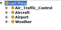
An ontology focuses mainly on classes which describe the concepts of the domain. It follows a hierarchical model where subclasses are all necessarily a part of the superclass (Noy & McGuinness, 2001). The ASDL ontology has four base classes: Air_Traffic_Control, Aircraft, Airport, and Weather. This can be seen in Figure 3 below. All these terms have been defined in Table 1.
| Term | Definition |
|---|---|
|
Air Traffic Control |
A service operated by appropriate authority to promote the safe, orderly and expeditious flow of air traffic. |
|
Aircraft |
Any machine that can derive support in the atmosphere from the reactions of the air other than the reactions of the air against the earth’s surface. |
|
Airport |
An area on land or water that is used or intended to be used for the landing and takeoff of aircraft and includes its buildings and facilities, if any. |
|
Weather |
The state of the atmosphere at a place and time as regards heat, dryness, sunshine, wind, rain, etc. |
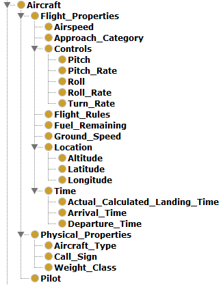
The main part of this ontology involves the aircraft and its properties. Figure 4 shows the subclasses of the Aircraft class. The Flight_Properties subclass describes the rules (IFR or VFR) that govern the flight, the speed of the aircraft, the fuel remaining and has three other subclasses: controls (pitch, roll and turn rates), location (altitude, latitude, longitude) and time (arrival time, departure time and Actual Calculated Landing Time). The physical properties subclass contains the call sign, type of aircraft and its weight class.
This ontology has been extended over time, with the departure extension
being added first, followed by the en route and reroute extensions,
respectively. This resulted in a language composition following an inside-out
approach, with the landing and departure phases being completed first,
followed by the middle
en route and reroute extensions. This
approach made it easier to determine missing components from both the
landing and departure stages, as inserting the middle extension was not
possible unless all components from both the landing and departure stages
were complete and accounted for. In addition, this approach allowed for ignoring
the more complicated components of flight, such as airspace
classifications and identification, until both the landing and departure
phases were implemented. This greatly simplified the already complicated
additions needed for completing the en route and reroute extensions, which
needed to modify the original ASDL structure.
The addition of three extensions resulted in only doubling the ontology, not tripling. This is because many terms already defined in the original ASDL ontology could be reused in the other phases of flight. This is common in aviation, where terms that are defined can span multiple phases of flights or domains. Therefore, it is believed that as further extensions are added to ASDL, the number of additional ontology terms needed to complete each extension may gradually decrease. This, in turn, suggests that future ASDL extensions can be added faster than previous extensions, given the future additions remain in a similar domain and/or subject area as the previous ones.
Departure Extension Ontology
The departure extension was similar to the original ASDL implementation in that both phases of flight involved an aircraft, pilot, and air traffic controller and their interactions in an airport environment. As a result, only a few additional ontology terms were needed to create a departure scenario. However, some additional terms were added for robustness in both the landing and departure scenarios, such as the weight properties of the aircraft.
Figure 5 shows the departure ontology terms added to the Air Traffic Control class of ASDL ontology. Note that some terms, such as Abort, are from the original ASDL ontology and do not reflect additions made for the departure extension; terms that were added in this extension are highlighted in red. These terms are used by air traffic control when communicating with a departing aircraft and provide additional control options. For example, the Line Up and Wait term is not required for every departure but can be used by ATC at airports with heavy traffic in order to expedite the departure process.
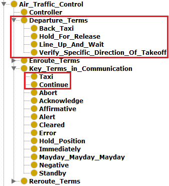
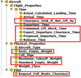
Figure 6 shows the departure terms added to Aircraft class of the original ASDL ontology. These terms define characteristics of the aircraft relevant to the departure phase, such as the aircraft’s maximum takeoff weight and the proposed departure time. In addition, the Pilot subclass was updated to contain an additional option a pilot may request during the departure phase.
En Route Extension Ontology
The en route extension introduced the concept of airspace and how aircraft move through different parts of an airspace. This required a variety of changes to the original ASDL ontology, which previously did not extend beyond a tower controller and airport airspace. As a result, a large amount of new terms was needed, especially in the ATC class. In addition, a new Airspace class was added in order to capture the movement of the aircraft through different parts of an airspace during the en route phase.
Figure 7 shows the en route ontology terms added to the Air Traffic Control class of ASDL ontology. These terms are used by air traffic control when communicating with an aircraft in the en route phase and provide additional control options. For example, the Traffic Alert term is not required for every aircraft in the en route phase but can be used by ATC if another aircraft may break the separation minima required between aircraft.
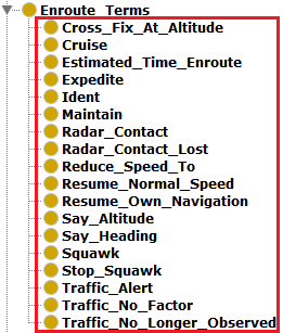
Figure 8 shows the Aircraft class updated with the en route terms. These terms define aircraft-specific components during the en route phase of flight, such as Miles-in-Trail, which is used by ATC for enforcing separation minima between two cruising aircraft.
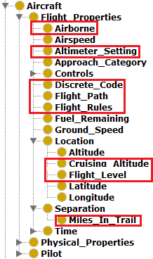
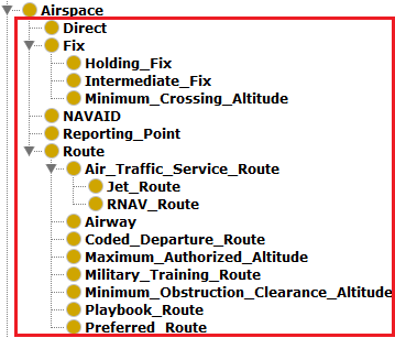
Figure 9 shows the new Airspace class. This class supports the movement of an aircraft through an associated airspace by defining the airspace components, such as routes and fixes. It should be noted that Route is not included as a term and instead acts only as a means of categorizing all sub-classifications of routes and the terms related to routes.
SES for Ontological Representation
The ontological representation of ASDL elements using SES is discussed in this section. The methodology of creating this schema representation was the same as that used to create the OWL ontology, and the data has been gathered from the same sources. The ontological details have been shown in tree-structure for better visualization. Figure 10 shows the high-level view of this SES representation.
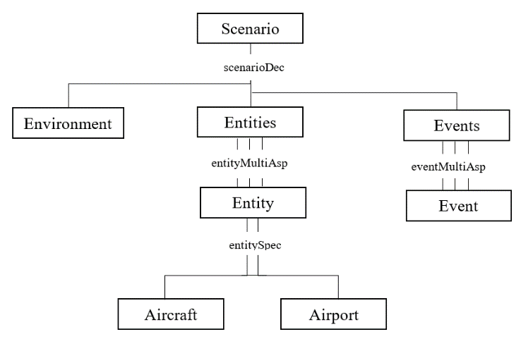
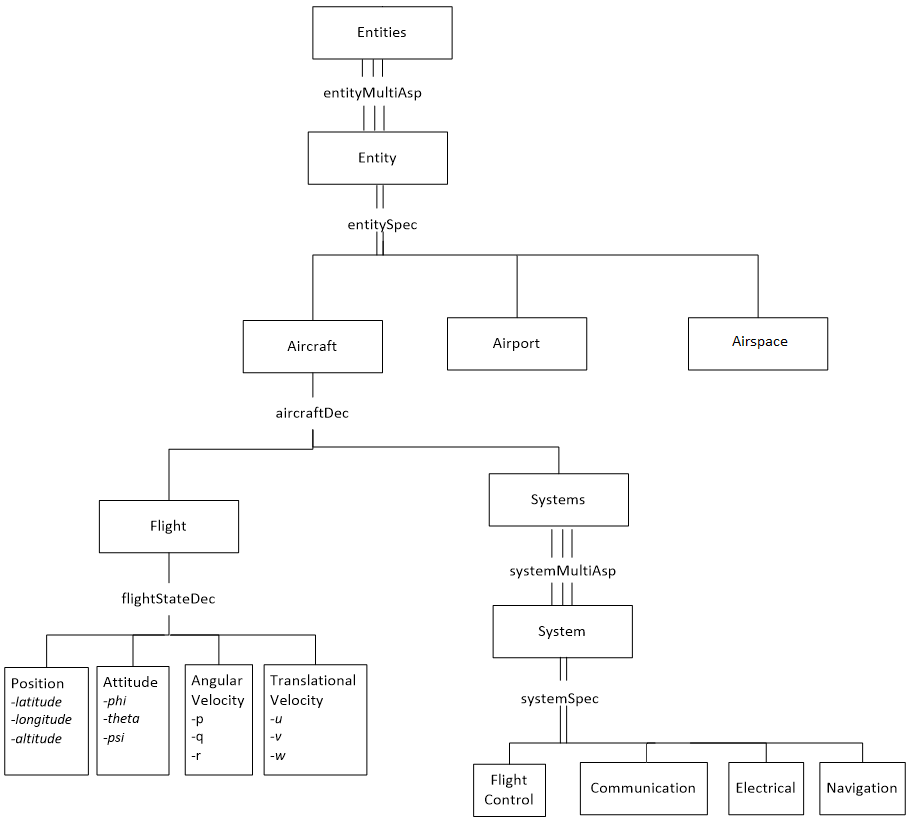
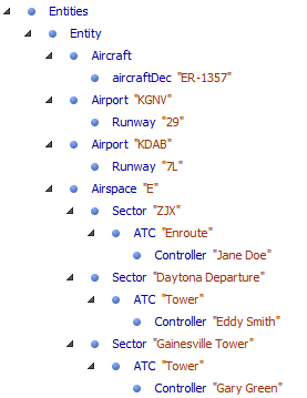
A scenario encapsulates the Environment in which all interaction takes place, the Entities that perform tasks or interact with each other and the Events that are triggered. The three main Entities are Aircraft, Airport and Airspace. The Aircraft entity can be seen in full in Figure 11.
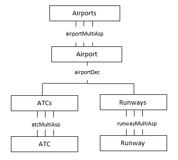
The Airport Entity contains a Runway and is associated with flights and scenarios. Figure 12 shows a full description of this SES element.
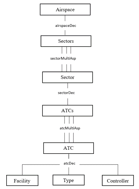
The Airspace entity contains a number of sectors, which contain several Air Traffic Centers (ATCs), which have a facility name, a type of center (such as Air Route Traffic Control Center for en route control, tower and terminal radar approach control). This has been shown in Figure 13.
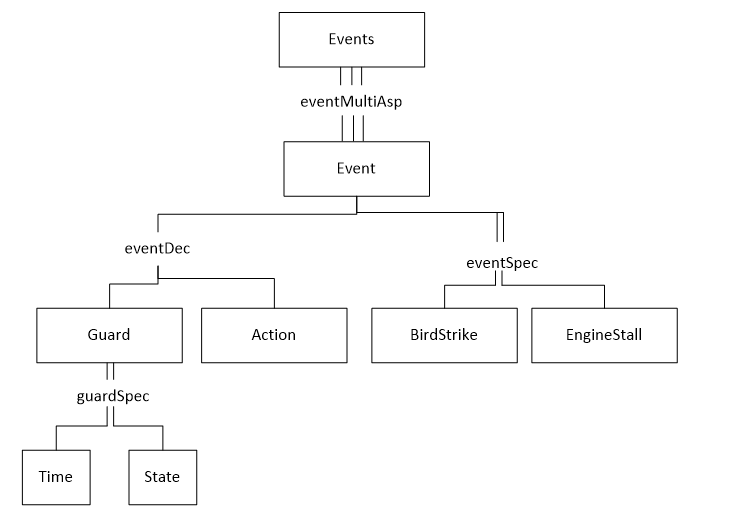
In addition to Entities, a Scenario also contains Events. These describe the changes to the Environment or Entity and their effects on the other elements of the Scenario. The changes in the state of an aircraft during flight are recorded using State Machines. Figure 14 shows the SES representation of Events in ASDL.
The state machines are composed of states and state transitions. We abstract the state transitions with an event. An event (state transition) has a guard condition and an action. Figure 15 shows the SES tree-structure for the state machine.
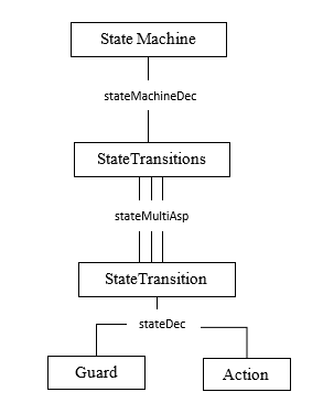
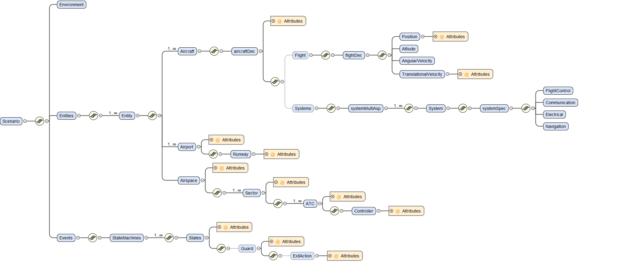
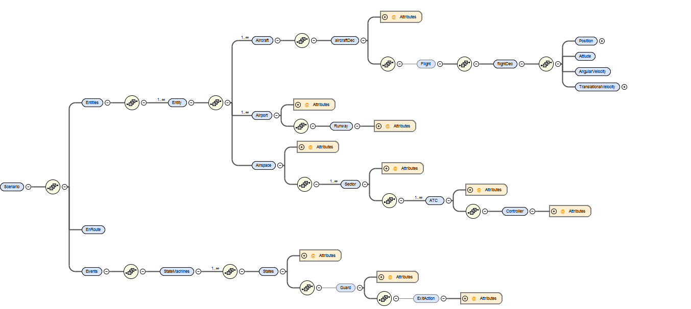
Figure 16 shows the overall view of ASDL in SES. All entities, events and properties can be observed here which make up the definition of all attributes of the language. The eXtensible Markup Language (XML) schema was generated for this model to define ASDL scenarios.
In the next section, we will present a sample en route scenario and model it using both approaches to scenario definition, that is, by using the EMF metamodel of ASDL, and the SES definition of ASDL.
Sample En Route Scenario
The use of both forms of the ASDL Ontology can be illustrated by defining a sample scenario using each method. An en route scenario describes the aircraft’s progression through airspace from the departure climb to the arrival descent. The en route scenario is defined as follows:
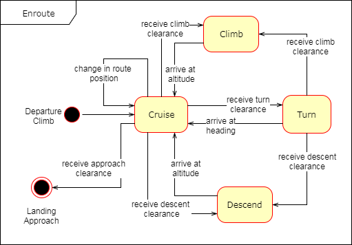
Aircraft ER-1357 has departed from the Daytona Beach International Airport (KDAB) via runway 7L. ER-1357 will be landing on runway 29 at the Gainesville airport (KGNV). Stable weather conditions nearing Daytona Beach are reported as calm winds, dew point: 23, sky condition: scattered clouds at 5500 feet, temperature: 15, visibility: 10. ER-1357 begins climbing and heads direct to the Ormond VOR (OMN). Daytona departure ATC grants ER-1357 to climb to 8000 feet and tells ER-1357 to proceed along the route as filed. ER-1357 begins to climb to 8000 feet. After passing OMN, ER-1357 joins airway T207-208. At CARRA, Daytona departure hands off ER-1357 to Jacksonville approach. ER-1357 turns west to join T208, heading towards KGNV. Once within 30 miles of KGNV, Jacksonville approach control contacts ER-1357 and the landing phase begins.
The state diagram for the en route extension is shown in Figure 17. During the en route phase of flight, the aircraft spends a majority of its time in the Cruise state, where the aircraft’s location on the route is constantly updating. At any time during the Cruise state, an aircraft may turn, climb, or descend as necessary to avoid traffic, follow the designated route, or as commanded by ATC. After arriving within approach range of the destination, the aircraft transitions into the landing phase, thereby ending the en route phase.
EMF En Route Scenario Implementation
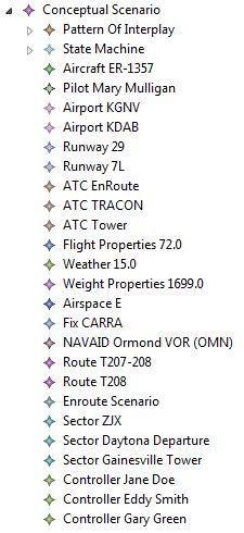
Figure 18 shows the EMF runtime implementation for the en route example scenario. expands the State Machine to show the aircraft’s movement through each state. It can be noted how this attribute closely follows the states and transitions seen in the state diagram in Figure 17.
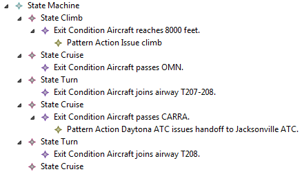
An excerpt from the en route scenario XML file is presented here. This portion of the scenario shows the definition of all states in the State Machine.
<stateMachines>
  <stateTransitions Name="Climb">
    <guard Name="Aircraft reaches 8000 feet.">
      <exitAction Name="Issue climb" Sequence="1" />
    </guard>
  </stateTransitions>
  <stateTransitions Name="Cruise">
    <guard Name="Aircraft passes OMN."/>
  </stateTransitions>
  <stateTransitions Name="Turn">
    <guard Name="Aircraft joins airway T207-208."/>
  </stateTransitions>
  <stateTransitions Name="Cruise">
    <guard Name="Aircraft passes CARRA.">
      <exitAction Name="Daytona ATC issues handoff to
                        Jacksonville ATC." Sequence="1" />
    </guard>
  </stateTransitions>
  <stateTransitions Name="Turn">
    <guard Name="Aircraft joins airway T208."/>
  </stateTransitions>
  <stateTransitions Name="Cruise"/>
</stateMachines>
SES En Route Scenario Implementation
The SES implementation allows for the same information to be entered which is present in the EMF metamodel. However, it implements it using an XML schema extracted from the tree structure of SES shown in Figure 16.
With the given SES tree consisting of all possible elements of the simulation scenario, the scenario modeling activity requires pruning of this tree to hand pick a very particular scenario. Pruning is defined as assigning the values to the variables and resolving the choices in Aspect, Multi-Aspect and Specialization relations. While there may be several Aspect nodes for several decompositions of the system on the same hierarchical level, a particular subset can be chosen in pruning based on the purpose. The resulting selection-free tree is the model representation of that particular scenario. The pruned version of the SES representation has been shown for an en route scenario in Figure 20.
The elements shown for the EMF model in Figure 19 are implemented in this pruned SES ontology to obtain the same type of graphical representation. The figure does not include all the elements to save space, but shows the basic structure to be similar to that obtained using EMF. Figure 21 shows this graphical representation of entities using the SES definition of ASDL. The state machine for this scenario using SES is seen in Figure 22 and is comparable to that obtained using EMF in Figure 19.
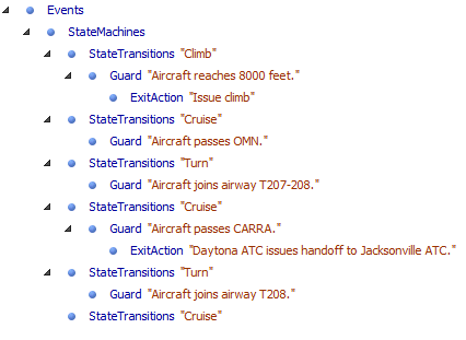
The XML depiction of the state machine using this process is presented here.
<StateMachines>
  <StateTransitions Name="Climb">
    <Guard Name="Aircraft reaches 8000 feet.">
      <ExitAction Name="Issue climb" Sequence="1" />
    </Guard>
  </StateTransitions>
  <StateTransitions Name="Cruise">
    <Guard Name="Aircraft passes OMN."/>
  </StateTransitions>
  <StateTransitions Name="Turn">
    <Guard Name="Aircraft joins airway T207-208."/>
  </StateTransitions>
  <StateTransitions Name="Cruise">
    <Guard Name="Aircraft passes CARRA.">
      <ExitAction Name="Daytona ATC issues handoff to
                        Jacksonville ATC." Sequence="1" />
    </Guard>
  </StateTransitions>
  <StateTransitions Name="Turn">
    <Guard Name="Aircraft joins airway T208."/>
  </StateTransitions>
  <StateTransitions Name="Cruise"/>
</StateMachines>
As can be seen from the excerpts, an identical XML scenario is produced using two different mechanisms and representations of the ASDL ontology.
ASDL Standardization
A well-known problem in the aviation simulation community is the complexity of simulators and variety in simulator designs. This commonly results in individual implementations of scenarios which work only on a specific simulator system. Standardization of ASDL creates a more accessible means of defining aviation scenarios which are reusable, easier to understand, and reduce error through reduced complexity. By following the Simulation Interoperability Standards Organization (SISO) standardization guidelines and procedure, ASDL can become a full-fledged standard providing a general, stable, and supported means of defining scenarios for use in aviation in ways that are not limited to a specific simulator design.
SISO Standardization Process
SISO is an international organization dedicated to the promotion of interoperability and reuse in the M&S community (Simulation Interoperability Standards Organization, 2017b). SISO publishes a variety of standards which strive to meet this goal in a variety of simulation domains, including analysis, research and development, testing and evaluation, and training. These standards provide a common base for creating reusable simulation components. However, becoming a SISO standard is not an easy task. SISO standards need to be stable, well understood, technically competent, have multiple independent interoperable implementations, be well received by the community, and be recognizably useful to the M&S community (Simulation Interoperability Standards Organization, 2017a).
There is a six-step process to becoming a SISO standard: (1) Activity Approval, (2) Product Development, (3) Forming Balloting Group and Product Balloting, (4) Product Approval, (5) Interpretation, Distribution and Configuration Management, and (6) Periodic Review. After being nominated to become a SISO standard, the product must apply for formal SISO approval. The proposal may be based on work previously done by an external organization. If the proposal is approved, the product begins development, following SISO standards, by a Product Development Group (PDG), which is assigned to the project. The PDG then presents the status of the product for approval to begin balloting to become a full-fledged standard. If more work on the product is needed, it goes back to the product development step. Otherwise, it moves into product approval. If the product demonstrates adherence to SISO principles for inclusion as a SISO standard, it is accepted by a committee. Once approved, a Product Support Group (PSG) takes responsibility of the product and handles the distribution and configuration management for the product and provides support to the community for the product. Finally, the PSG will periodically review each product to ensure they are still relevant to the community and they continue to meet SISO requirements (Simulation Interoperability Standards Organization, 2017c).
In 2008, the Military Scenario Definition Language (MSDL) standard was accepted and published as a SISO standard. Reaffirmed in 2015, this standard defined an XML-based language for defining military scenarios. The intent of MSDL was to create a general and reusable method of creating and verifying military scenarios, improve consistency among scenarios, and create reuse of scenarios between different simulators through a standard scenario language format (Simulation Interoperability Standards Organization, 2008).
ASDL was created with MSDL as a source of inspiration, as both languages share a similar domain of scenario generation and application. However, ASDL addresses scenario generation for the aviation domain, which is not addressed or supported through MSDL. Similar to the MSDL, ASDL is defined using an XML schema that allows for format standardization and content verification. This definition of ASDL should be used towards applying for SISO standardization.
DSL Standardization Challenges
In addition to being incredibly difficult to create, DSLs are also difficult to standardize. An examination of the Battle Management Language (BML) standardization efforts identified three major problems that can delay or inhibit the standardization of a domain language: (1) the technical readiness, (2) the need for a deliberate process, and (3) the adequacy of resources to pursue standard development. After over five years of standardization efforts, BML was still unable to be accepted as a SISO standard. One of the major factors in this result was the lack of technical readiness. Technical readiness includes the need for multi-disciplined support and multiple perspectives, technology advancement, and emergent requirements. BML is a wide-spread, large-scope language that requires a vast amount of technical expertise across a variety of domains, including all branches of the military. In addition, as technology continued to mature, BML requirements and the systems used by BML changed. For example, while attempting to standardize BML, the underlying data model was continually updated and revised, leading to inconsistencies and issues with the standardization. These problems significantly delayed the standardization process for BML. In addition to technical readiness issues, BML was required by the SISO standardization process to follow a deliberate process which proved the need for and competency of the language. However, this was incredibly difficult to achieve for a project of this size and style. BML was being developed piecemeal, by contributors and volunteers from all over the world. This distributed development style led to copious misunderstandings and trust issues amongst the team. The team became fractured and meaningful development slowed to a crawl. The team also lacked resources to achieve the goal of standardization. While volunteers keep the costs of development lower, it can lead to issues in motivation and drive. As a result, the development schedule can suffer from a lack of direction and motivation from a single driving point, such as a sponsor. In addition, because SISO standards strive for openness and accessibility, tension was created between leaders trying to drive a project forward and those implementing the project. A strong understanding of the technical domain and a homogeneous team culture are necessary to avoid these fatal standardization problems (Abbot, Pullen, & Levine, 2011).
Discussion and Future Work
This paper examined the ontological development of ASDL using two different methods. For the first, the ontology was created in the OWL format using an open-source ontology editor called Protégé. This ontology was then used to create an EMF metamodel of the language and an XML schema was produced using automated model transformations and code generation. In the other approach, the ontology was defined in the form of SES entities and relationships. This tree structure of SES was used to obtain the XML schema. The XML script of a sample en route scenario was obtained using both methods and found to be identical. However, as the results are indistinguishable, both approaches are valid and suited to the purpose of creating a scenario definition language in aviation. A comparison of the two approaches has been presented in Table 2.
| Characteristics | OWL/EMF | SES/XML |
|---|---|---|
|
Required attributes |
Entities and relationships |
Entities, relationships and quantities |
|
Specification structure |
Hierarchical |
Tree structure |
|
Ontology format |
.owl file |
Graphical |
|
Scenario output format |
XML |
XML |
|
Framework independence |
No; dependent on EMF |
Yes |
It was found that entities and relationships are required at the start to define a scenario using both approaches. The specification format for OWL is hierarchical, whereas SES follows more rigid guidelines and restrictions in the definition of entities, aspects and specializations. The EMF ontology is in a standard web ontology language format (.owl file), whereas the SES is in a graphical format. An OWL file requires an additional tool to open and edit the file, while working with SES can be done using any graphical editor. However, due to the specialized structure, an understanding of SES is required to comprehend and edit these files. The authors found that the SES approach did not require the additional step of transforming the ontological details into an EMF model, but rather required its definition using an XML tool. It also removed the dependency on the Eclipse framework during the development stage. Ultimately, both approaches produced an identical scenario in XML format.
As ASDL is still in its infancy, the next step is to expand the language to describe scenarios in better detail than is currently possible. The language needs to be extended to cover a wider variety of scenarios such as flight training, air traffic controller training, and unmanned vehicle flight. This work done for ASDL is a stepping stone to the standardization of the language as a method for defining aviation scenarios. The process for standardizing such a language has been described here along with some of the challenges facing this effort.
Bibliography
- Abbot, J., Pullen, J., & Levine, S. (2011). Answering the Question: Why a BML Standard Has Taken So Long to Be Established?. In IEEE Fall Simulation Interoperability Workshop. Orlando, FL.
- Alatrish, E. (2013). Comparison Some of Ontology Editors. Management Information Systems, 8(2), 18–24.
- Bechhofer, S. (2009). OWL: Web Ontology Language. In Encyclopedia of Database Systems (pp. 2008–2009). Boston: Springer US.
- Chhaya, B., Jafer, S., Coyne,
W., Thigpen, N., & Durak, U. (2018). Enhancing Scenario-Centric Air
Traffic Control Training. In AIAA Modeling and Simulation
Technologies Conference (p. 1399). Kissimmee, FL: American Institute of Aeronautics and Astronautics.

- Durak, U., Topcu, O., Siegfried, R., & Oguztuzun, H. (2014). Scenario Development: A Model-Driven Engineering Perspective. In Simulation and Modeling Methodologies, Technologies and Applications (SIMULTECH), 2014 International Conference on (pp. 117–124). Vienna: IEEE.
- Durak, U., Pruter, I., Gerlach,
T., Jafer, S., Pawletta, T., & Hartmann, S. (2017). Using System
Entity Structures to Model the Elements of a Scenario in a Research
Flight Simulator. In AIAA Modeling and Simulation Technologies
Conference (p. 1076). Grapevine, TX: American Institute of Aeronautics and Astronautics.
- Durak, U., Jafer, S., Wittman,
R., Mittal, S., Hartmann, S., & Zeigler, B. (2018). Computational
Representation for a Simulation Scenario Definition Language. In AIAA Modeling and Simulation Technologies Conference (p. 1398). Kissimmee, FL: American Institute of Aeronautics and Astronautics.
- Federal Aviation Administration (1995). Order JO 7110.65J, Air Traffic Control. Federal Aviation Administration.
- Federal Aviation Administration
(2012). AFS Flight Program Flight Operations Manual. Federal
Aviation Administration.

- GSD Product Development Group
(2014). Guideline on Scenario Development for Simulation
Environments. Orlando, FL: Simulation Interoperability Standards
Organization.

- Jafer, S., Chhaya, B., Durak,
U., & Gerlach, T. (2016). Formal Scenario Definition Language for
Aviation: Aircraft Landing Case Study. In AIAA Modeling and
Simulation Technologies Conference (p. 3521). Washington, D.C.:
American Institute of Aeronautics and Astronautics.
- Jafer, S., & Durak, U.
(2017). Tackling the Complexity of Simulation Scenario Development in
Aviation. In Proceedings of the Symposium on Modeling and
Simulation of Complexity in Intelligent, Adaptive and Autonomous
Systems (p. 4). Pasadena, CA: Society for Computer Simulation
International.
- Mernik, M., Heering, J., &
Sloane, A. (2005). When and How to Develop Domain-Specific Languages. ACM Computing Surveys (CSUR), 37(4), 316–344.
- NATO Modelling and Simulation
Group MSG-086 (2015). Guideline on Scenario Development for
(Distributed) Simulation Environments (Report No. TR-MSG-086-Part-II). The NATO Science and Technology Organization.
- Noy, N. F., & McGuinness,
D.L. (2001). Ontology Development 101: A Guide to Creating Your
First Ontology. Stanford, CA: Knowledge Systems Laboratory, Stanford University.
- Pawletta, T., Schmidt, A., Zeigler, B., & Durak, U. (2016). Extended Variability Modeling using System Entity Structure Ontology within MATLAB/Simulink. In Proceedings of the 49th Annual Simulation Symposium (pp. 62–69). Pasadena, CA: The Society for Modeling & Simulation International.
- Protégé Home Page. (2018, March
23).

- Putten, B., Wolfe, S., &
Dignum, V. (2008). An Ontology for Traffic Flow Management. In The
26th Congress of ICAS and 8th AIAA ATIO (p. 8946). Anchorage, AK:
Aviation Technology, Integrations, and Operations (ATIO) Conference.
- SESAR (2018, March 23). EUROCONTROL ATM Lexicon.
- Simulation Interoperability Standards Organization (2008, October 14). SISO-STD-007-2008, Standard for Military Scenario Definition Language (MSDL). Orlando, FL: Simulation Interoperability Standards Organization.
- Simulation Interoperability
Standards Organization (2017a). What is a Standard?.
- Simulation Interoperability
Standards Organization (2017b). Overview of SISO: Who We Are
and What We Do.
- Simulation Interoperability
Standards Organization (2017c). The Six-Step Process.
- Yao, Z., & Zhang, Q.
(2009). Protégé-Based Ontology Knowledge Representation for MIS Courses.
In International Conference on Web Information Systems and
Mining (pp. 787–791). Shanghai: IEEE.
- Zeigler, B. (1984). Multifacetted Modelling and Discrete Event Simulation. New York, NY: Academic Press.
- Zeigler, B. (2000). Theory of Modeling and Simulation. (2nd). New York: Wiley Interscience.
- Zeigler, B., & Hammonds, P. (2007). Modeling and Simulation-based Data Engineering. Burlington, MA: Academic Press.
Copyright Information
 Copyright © 2018 Shafagh Jafer, Bharvi Chhaya, Jessica Updegrove, Umut Durak. This article is licensed under a Creative Commons Attribution 4.0 International License.